VLF AC WITHSTAND TESTING of CABLE
Voltage Levels & Time Durations of Test
VLF cable test voltages and time durations are set by IEEE Standard 400.2-2013.
There are no “rules of thumb” to be used. These numbers result from many years of VLF field use and research.

Testing Summary

The above information describes VLF Withstand testing, where the intent of the test is to apply a sufficient test voltage for a long enough time to permit any severe defects driven into partial discharge to fail within the test duration. If a defect can’t withstand the test voltage, let it fail and make the repair or replacement. If the cable holds, the operator has a high assurance that the cable should not fail in service for many years.

Diagnostic Testing

If a pass/fail AC Withstand test is not desired, there are several qualitative Diagnostic Tests available. Using the VLF as the over voltage source, Tangent Delta (δ) measurements and Partial Discharge detection and location tests can be performed with accessories added; available from HVI.

Testing Methodology

When VLF Withstand testing cable, the proper test voltage and time duration are critical for the success of the test. If a VLF test is too low in voltage and/or too short in duration, more harm than good may result. Perform the test as instructed to make best use of VLF technology. Once partial discharge is triggered in a defect under the test voltage, enough time must be allowed to permit the PD to create an electrical tree and grow to failure. The test voltage and time duration are both critical to causing failures at defect locations severe enough to be triggered into PD during the test. Let the technology and physics work. Lesser defects are not affected, as they are not forced into PD under the test voltage. They remain dormant and are not aggravated by the test voltage since it is below the PD inception voltage level of the defect.

IEEE Std. 400.2-2013
EEE Guide for Field Testing of Shielded Power Cable Systems Using Very Low Frequency (VLF) (less than 1 Hz)
Table 3 - VLF withstand test voltages for sinusoidal and cosine-rectangular waveforms (see note 1*)
Note 1

If the operating voltage is a voltage class lower than the rated voltage of the cable, it is recommended that the maintenance test voltages should be those corresponding to the operating voltage class.

Note 2

The maintenance voltage is about 75% of the acceptance test voltage magnitude.

Note 3

Some existing test sets have a maximum voltage that is up to 5% below the values listed in the table. These test sets are acceptable to be used. However, there is a risk that the cable may be “understated” due to a combination of lower test voltage and allowed uncertainty of the measuring circuit.

VLF ac voltage testing methods utilize ac signals at frequencies in the range of 0.01 Hz to 1 Hz. The most commonly used, commercially available VLF ac voltage test frequency is 0.1 Hz. VLF ac test voltages with cosinerectangular and the sinusoidal wave shapes are most commonly used. While other wave shapes are available for testing of cable systems, recommended test voltage levels have not been established.

5.1 GENERAL VLF AC WITHSTAND VOLTAGE TESTING
Voltage Levels & Time Durations of Tests
The purpose of a withstand test is to verify the integrity of the cable under test.
It should be noted that the recommended test time for a withstand test is 30 min.
5.1.1 VLF ac withstand voltage test parameters

The purpose of a withstand test is to verify the integrity of the cable under test. If the test cable has a defect severe enough at the withstand test voltage, an electrical tree will initiate and grow in the insulation. Inception of an electrical tree and channel growth time are functions of several factors including test voltage, source frequency and amplitude, and the geometry of the defect. For an electrical tree from the tip of a needle in PE insulation in laboratory conditions to completely penetrate the insulation during the test duration, VLF ac voltage test levels and testing time durations have been established for the two most commonly used test voltage sources, the cosine-rectangular and the sinusoidal wave shapes. However, the time to failure will vary according to the type of insulation such as PE, paper, and rubber. Thus the electrical tree growth rate is not the same for all materials and defects.

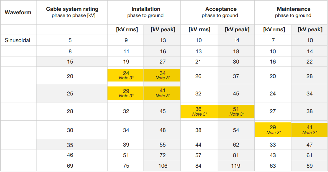
The voltage levels (installation and acceptance) are based on the most used, worldwide practices of from less than 2 U0 to 3U0, where U0 is the rated rms phase to ground voltage, for cables rated between 5 kV and 69 kV. The maintenance test level is about 75% of the acceptance test level. One can reduce the test voltage by another 20% if the voltage is applied for longer times (Bach [B2]; Baur, Mohaupt, and Schlick, [B6]; Krefter [B27]). Evidence (Hernandez-Mejía, et al. [B21]) indicates that increasing the voltage above 3U0 to compensate for reduced test cycles (time) does not replicate performance either on test or in service as compared to the lower voltage, longer time tests.

Table 3 lists voltage levels for VLF withstand testing of shielded power cable systems using cosine-rectangular and sinusoidal waveforms (Bach [B2]; Eager, et al. [B9]; Krefter [B27]; Moh [B28]). For a sinusoidal waveform the rms is 0.707 of the peak value, assuming the harmonic distortion is less than 5%. The rms and peak values of the cosine-rectangular waveform are assumed to be equal. It should be noted that terminations may need to be added to avoid flashover for installation tests on cables rated above 35 kV. Regarding the test times:

The recommended minimum testing time for a simple withstand test on aged cable circuits is 30 min at 0.1 Hz (Goodwin, Oetjen, and Peschel [B13]). If a circuit is considered as important, e.g., feeder circuits, then consideration should be given to extending the testing time to 60 min at 0.1 Hz (Hampton, et al. [B19].

The recommended minimum testing time for an installation and/or acceptance withstand test on new cable circuits is 60 min at 0.1 Hz.

A test time within the range 15–30 min may be considered if the monitored characteristic remains stable for at least 15 min and no failure occurs. It should be noted that the recommended test time for a withstand test is 30 min.

CONSULT HVI FOR FURTHER INFORMATION ON VLF TESTING AND ANY OTHER HIGH VOLTAGE TESTING APPLICATION